MetaDAQ VDE Buch-Beitrag VIP2011 Fürstenfeldbruck
Automated microvibration measurements on spacewheels
Dipl. Phys. Andreas Hergesell
MetaDAQ, Ingenieurbüro für innovative Messtechnik
Abstract
Spacewheels are used for stabilized attitude control of spacecrafts. Those wheels are mission critical high precision devices which have proven their reliability for decades. Due to their mechanical nature they create some small amount of mechanical noise. Those microvibrations may affect the satellite and sensitive payload instruments. Today high precision data acquisition devices and modern measurement software are used to gain detailed knowledge about the sources and levels of microvibration. Automatable software can ease the extensive tasks of acquisition, storage, analysis and presentation of large vibration data sets. This article starts with a draft of the p
rincipal design and mode of action of spacewheels. Then we describe a measurement setup, sensors and data acquisition devices used for phase synchronous 3D measurement of vibration signals. Finally we will focus on the MyVibSystem (MVS), a measurement solution which can automate measurement and analysis on rotary machine. The software is designed in LabVIEW using a concurrent active objects approach. It makes use of National Instrument’s SVMS.
Kurzfassung
Stabilisierungsräder (SR) werden seit langem erfolgreich zur Lageregelung von Flugkörpern in der Raumfahrt eingesetzt. SR sind bewährte Präzisionsgeräte die jedoch aufgrund ihres mechanischen Aufbaus kleinste mechanische Schwingungen (Mikrovibration) erzeugen. Diese können empfindliche Nutzlasten wie z.B. Teleskope unerwünscht beeinflussen. Um die Mikrovibration in Amplitude und spektraler Verteilung zu vermessen, werden heutzutage präzise Datenerfassungsgeräte und automatisierbare Software eingesetzt. Derartige Software kann den aufwendigen Prozess von Datenerfassung, Speicherung, Analyse und abschließender Berichterstellung erheblich vereinfachen. Zu Beginn des Artikels wird das Funktionsprinzip eines SR skizziert. Danach werden ein Messaufbau und die Sensorik für eine simultane, phasensynchrone Mehrachsenmessung skizziert. Abschließend wird die Messlösung MyVibSystem (MVS) vorgestellt, mit der automatisierte Vibrationsmessungen an rotierenden Prüflingen durchgeführt werden können. Die Software wurde einen Active-Object-Ansatz verfolgend in LabVIEW entwickelt und verwendet Komponenten der NI Sound and vibration measurement suite SVMS.
What are spacewheels used for?
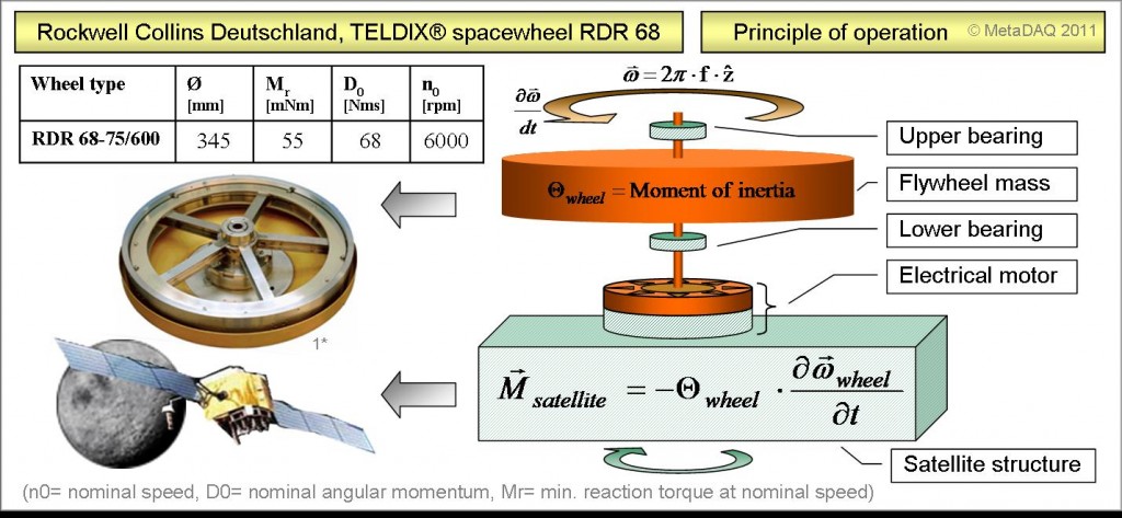
Spacewheels are used for stabilization and orientation of satellites in space. A satellite in space is exposed to different external forces which would change its spatial orientation over time. There is friction, gravitational and magnetic effects as well as particle pressure from solar wind (photons, protons, etc.). Generally precise orientation and stabilization is required to allow for proper operation of the satellite and its payload (directional antennas, telescopes and so forth).
Figure 1: Spacewheel, physics, principle of operation
Here spacewheels come into play. Very simplified, spacewheels are flywheels, optimized for high moment of inertia and low noise. They are supported by advanced ball bearings and are driven by an electrical motor. There are two types of wheels: momentum wheels and reaction wheels. Momentum wheels spin at a fixed speed and their angular momentum stabilizes a satellite perpendicular to the rotational axis. On the other hand reaction wheels are used to rotate a satellite parallel to the axis of the spinning flywheel. If motor torque is applied to their flywheel, the opposite torque is applied to the satellites structure. As the wheel accelerates, the satellite turns in the opposite direction: actio = reactio. If you combine three or more spacewheels into a so called flight set, you are able to control and stabilize the attitude of a spacecraft in 3D.
Imbalance and ball bearing imperfections as sources of microvibration
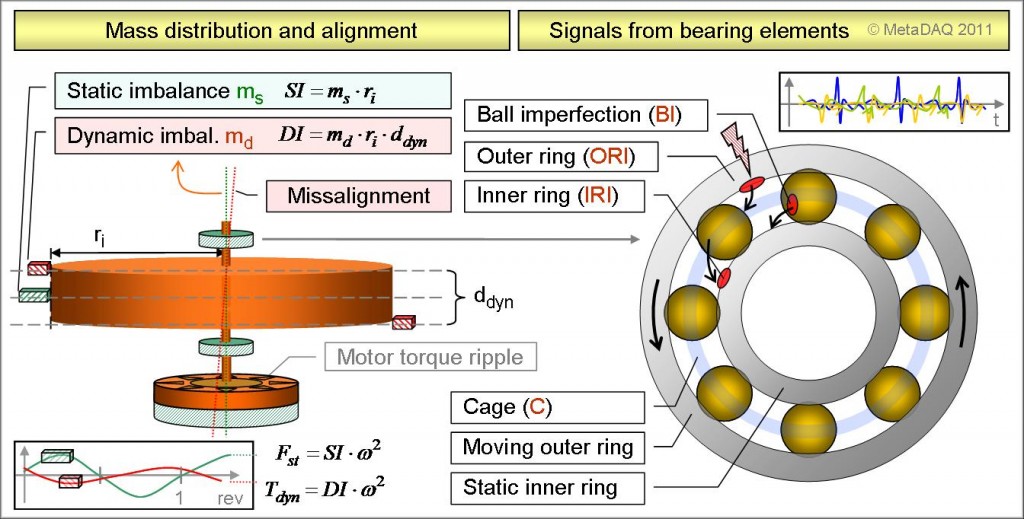
There are different sources for vibration signals coming from spacewheels under operation. Imbalance is one of them. As shown on the left part of figure 2, a so called static imbalance occurs if the center of mass of the flywheel resides outside the axis of rotation. This imbalance can be represented by a single mass (ms) at distance ri. A so called dynamic imbalance arises in case of a misalignment of the axis of principal inertia of the flywheel and the spin axis. It can be represented by two masses (md) separated by 180° at distance ri and vertical distance ddyn [2]. Both imbalances create sinusoidal signals occurring once per revolution. They are signals of order 1.0. Order 1.0 means: A signal occurs once per revolution. A signal periodically occurring 1.42 times per revolution is called to be of order 1.42, and so on. But where might non integer orders come from?
Figure 2: Sources of microvibration
In figure 2 on the right we see a ball bearing with fixed inner ring and the outer ring turning counter-clockwise (CCW). As the outer ring turns, the balls also roll CCW but obviously with lower angular group velocity. A defect at the outer ring (ORI: outer ring imperfection) will therefore overhaul the balls and any passing-by of the defect will create a small vibration signal of a specific order. Its order will be obviously larger then 1.0 and probably non integer. Ball imperfections (BI) will “crash” in the outer and inner ring and will also create signals of specific orders. The same holds for inner ring imperfections (IRI) which are overrun by the balls passing by. The orders of those signals are determined by the geometry of the ball bearing.
The ball bearing signals add on top of the imbalance signals described earlier. Altogether, those signals propagate through the spacewheel and possibly into the satellite. Structural dynamics are involved as well: Resonances of the flywheel or its housing can be crossed by signal orders which are amplified then. But this is out of scope for this article.
3D dynamic force measurements
The level and spectral distribution of microvibrations have to be known to take appropriate countermeasures. To find all relevant signal components, a wheel needs to be operated over its whole specified operating range (e.g. ± 6000 RPM). Since we want to perform vibration measurements, we need phase synchronous, high precision acquisition devices with hardware anti-aliasing filters. We use National Instruments PXI-4472B DSA devices which can be synchronized and are well suited for this task. They have 110dB dynamic range, different input coupling modes including IEPE and sampling rates of up to 102 kHz. The spacewheel under test is mounted on top of a Kistler three axis dynamometer which allows for 3D dynamic force and torque measurements.
Figure 3: Measurement setup for 3D dynamic force measurements
The force signals are amplified by a Kistler charge amplifier and fed into the PXI-4472 DSA boards. The spacewheel shown is controlled by an Universal Wheel Interface (UWI) of Rockwell Collins Deutschland GmbH (RCD). An UWI can operate TELDIX® Space Wheels and exposes a unified serial command interface for different wheel families of RCD. It provides protection, logic and drive electronics. All components are connected to an appropriate multi core workstation.
Vibration measurement files can be large. A 40 minutes measurement with 16 channels @ 50KHz sampling rate consumes more than 7 gigabyte disc space, even in 32Bit data representation. Because such files would be unhandy, better a measurement software splits them up into smaller chunks and keeps track of data location, organization and associated metadata.
Analysis of vibration data sets of rotary machinery
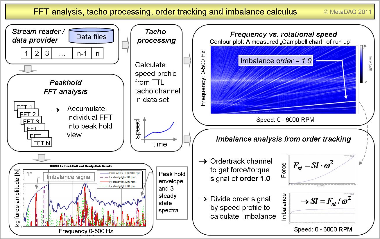
For analysis of large vibration datasets, a streaming approach is used. The measurement data is divided into blocks which are processed consecutively. During FFT processing of those blocks a peak-hold view can be aggregated to get an overview of the worst-case amplitudes that have occurred during a measurement session.
Bearing vibration signals are related to rotational speed. The speed profile can be calculated from a digital tachometer signal which is stored in one of the measurement channels.
Figure 4: Spectral measurements, tacho processing and order tracking
To calculate the static and dynamic imbalance of the wheel under test, the first order (1.0) is extracted from the respective force and torque channels by order tracking. The imbalance-orders are then divided by the square of the corresponding speed profile to gain the imbalance information.
Automated measurements using the MyVibSystem software
The MyVibSystem (MVS) is a software suite used to perform automated measurements, analysis and reporting on large vibration data sets of rotary devices. The software is developed in the graphical programming language LabVIEW of National Instruments. LabVIEW’s inherent parallelism and dataflow paradigm make it an ideal choice for development of concurrent software. The MVS is built on top of MetaDAQ’s framework FW3, which is designed to build distributed scalable and robust concurrent applications. This reuse framework implements an active object plug-in architecture which allows dynamic runtime instantiation of so called modules.
Figure 5: Active objects software architecture of the MyVibSystem
Each module is an autonomous piece of software (an active object) and contains a number of dedicated threads. Each thread can receive and send messages to any other object by using communication queues. A standard FW3-module consists of 5 threads (Core, GUI, cmd parser, data and driver). Some threads contain state machines for self paced operation. The configuration shown in figure 5 consists of 75+ threads and of 4500+ virtual instruments and control files. Modules like the DSA data acquisition module act as data sources. Other modules like display objects, realtime analysis, data storage and so on, act as data sinks. Data and command links between modules are dynamically established using a publish/subscribe pattern [3]. The framework supports distributed computing over TCP/IP and allows network integration of NI’s PAC platform cRIO/sbRIO as well.
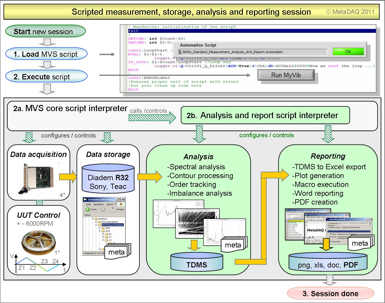
A special feature of the framework is its scripting ability. Beside manual GUI input, most MVS commands can be executed using a purpose-built scripting language. Script interpreters can execute scripts in a linear fashion. But the interpreters themselves can be executed simultaneously and control the inherent parallel universe of the active objects. Script interpreters can exchange data using variables. This technique allows automating and synchronizing different domains of the software at the same time.
Figure 6: Automated “two click” measurement session on a spacewheel
E.g. the data acquisition and storage module can be controlled while another script is executing a thermal profile in a climatic chamber. The MVS script language is like a basic dialect, with typed local and global variables, flow control and error handling. The parsers and interpreters are developed in LabVIEW as well.
In Figure 6 you see a “two click” measurement session with MVS. The operator loads a script and starts its execution. Now the core interpreter configures and starts the data acquisition and storage module. The vibration data is being stored along with header data and metadata. After the measurement is done, the analysis script interpreter is started and configures and controls the analysis and reporting modules. The analysis module stores its results and associated metadata in TDMS files. Those files provide all data for automated report generation. The reporting module finally transfers the analysis results into a user-provided MS-EXCEL template. The reporter also renders all requested data views and stores them as PNG-pictures. Additionally user macros can be executed. Finally a MS-WORD template is linked to the EXCEL file to create a user report with individual layout. As a last step the WORD report is converted into a PDF document and saved to disc. A typical measurement session takes about 80 minutes with 30-90 minutes subsequent analysis and reporting, depending on the level of detail required.
Summary
We have discussed the principle of operation of spacewheels and described imbalance and ball bearing signatures as possible sources of microvibration. We have described a measurement setup for dynamic 3D force measurements on a spacewheel under operation. The MyVibSystem was introduced as an automatable measurement solution for acquisition, storage, analysis and reporting on large vibration datasets of rotary machinery. The software is based on a concurrent active object framework, designed for development of robust distributed large scale applications. It is designed in LabVIEW and makes use of National Instruments sound and vibration measurement suite SVMS. Finally we’d like to thank the wheel-specialists of Rockwell Collins Deutschland GmbH – a leading supplier for space technology and TELDIX® spacewheels – for their cooperation, the supply of sample data and pictures used for this article.
References
[1]: Horst Heimel, “SPACEWHEEL MICROVIBRATION – SOURCES, APPEARANCE, COUNTERMEASURES”; GNC 2011, 8th Inernational ESA Conference, Rockwell Collins Deutschland GmbH, 2011
[2] Bill Bialke, “Microvibration disturbance fundamentals for rotating mechanisms”, 34th Annual AAS Guidance and Control Conference, Breckenridge, CO, Feb. 2011
[3] Gang Of Four, GOF. Erich Gamma, Richard Helm, Ralph Johnson, John Vlissides (GoF), “ Design Patterns. Elements of Reusable Object-Oriented Software”, 1995, Addison-Wesley
Figures and pictures
[1*] in Figure 1,3,5,6: Courtesy of Rockwell Colllins Deutschland GmbH
[2*] in Figure 3: Courtesy of Kistler Instrumente AG, Winterthur, Schweiz
[3*] in Figure 3: Courtesy of Vötsch Industrietechnik GmbH, Balingen
[4*] in Figure 6: Courtesy of National Instruments GmbH, München
Brand names, product names, and manufacturer names, as well as trademarks, company logos, and all other data of other manufacturers/companies/suppliers, are only be used for references and are property of the respective owners.


